Is There Enough Pressure?Fuel Injection Diagnosis & ServiceBy Larry Carley, technical editorOne of the first questions that should always be asked — and answered — when diagnosing a fuel-related complaint on a fuel injected engine is, “What is the fuel pressure?” All too often, technicians assume fuel pressure is “good” without actually measuring it with a gauge. If the engine runs, they assume the injectors are getting adequate fuel pressure. If the engine cranks but won’t start, and they depress the service valve on the fuel rail and some fuel squirts out, they assume the injectors have pressure. They do, but the question remains, “How much pressure?” For the engine to start and run smoothly with no stalling, hesitation or misfiring, the injectors have to deliver the proper amount of fuel with every squirt. This is especially important on late-model engines with sequential fuel injection. One bad injector will cause a noticeable misfire and usually set a P030X misfire code (where X represents the cylinder that is misfiring). On older engines where the injectors are all fired simultaneously, the good injectors can often compensate for one or two bad injectors. Even so, for the engine to run right, fuel pressure to the injectors is critical as is the volume of fuel delivered by each injector when it fires.
It’s All About Fuel Pressure On certain Jaguar engines, for example, the factory spec calls for 37 psi of fuel pressure. If you see 36 psi or 38 psi, you need to replace the fuel pressure regulator. Fuel Volume Is Just As Important The old rule of thumb that says a “good” fuel pump will flow about a pint of fuel in 15 seconds (half a gallon per minute) still holds true, but some engines need more than this. So the fuel delivery specifications also need to be looked up to see if the pump is delivering an adequate supply of fuel to the engine.
The flow meter can be hooked up to the supply line that runs to the fuel rail to measure flow. But Linder says a better method for checking fuel flow and pump capacity is to hook up the flow meter to the return line that runs from the fuel pressure regulator back to the fuel tank. Then check the return flow at idle, 2,500 rpm and 5,000 rpm. The volume of fuel flowing through the return line will drop as engine speed increases because more fuel is flowing through the injectors. Even so, the return flow for a good fuel pump with adequate pumping capacity at 5,000 rpm should still be about half the volume it had at idle (say 0.23 gpm versus 0.46 gpm). If the return flow at 5,000 rpm drops to 10% or less of the idle return flow rate, the fuel pump probably does not have enough reserve capacity to keep up with the engine when the engine is under load. The weak pump will starve the engine for fuel, causing it to misfire and lose power. Get The Right Replacement Pump What’s more, some parts suppliers have over-consolidated their fuel pump lines to reduce the number of SKUs needed to provide broad market coverage. Pump capacities can always be higher than specifications, but should never be lower. So if you get a pump that is flow rated at 0.4 gpm and you install it in a vehicle that requires 0.5 or 0.6 gpm, the pump may supply enough fuel at idle and low rpm, but may starve the engine at higher loads and speeds. Yet it is not a “bad” pump — just an under-rated pump for the application. Fuel Pressure Regulator Problems If fuel pressure is low, disconnect the vacuum hose to the regulator. You should see an increase in pressure if the regulator is not leaking. No change would indicate a bad regulator. Likewise, you can pinch or block the return line temporarily to see if pressure goes up. If it does, it means the regulator is bypassing too much fuel back to the tank and needs to be replaced. Also, check the vacuum hose to the regulator for the presence of fuel inside the hose (there should be none). Fuel in the hose means the diaphragm inside the regulator is leaking and the regulator needs to be replaced. Dirty Injectors It doesn’t take much of a restriction in an injector to lean out the fuel mixture. Only an 8% to 10% restriction in a single fuel injector can be enough to upset the air/fuel mixture and cause a misfire. Gasoline contains waxy compounds that can leave varnish deposits in the injectors when the fuel evaporates. These deposits tend to form after the engine is shut off. Heat from the engine causes residual fuel in the injector tips to evaporate.
On four cylinder engines, the #2 and #3 injectors are in the hottest location and tend to clog up faster than the end injectors on cylinders #1 and #4. The same applies to the injectors in the middle cylinders in six- and eight-cylinder engines. The hotter the location, the more vulnerable the injector is to clogging from heat soak. The cure for dirty injectors is to clean them (on-car, or off-car with special injector cleaning machine), or to replace them if cleaning fails to restore normal flow rate and nozzle pattern. Fuel Injector Electrical Checks One way to check the injectors is with an ohmmeter (key off). Disconnect the wiring connector from each injector, and measure the resistance between the injector’s terminals. Look up the specifications, don’t guess. Some specs may call for 2 to 3 ohms of resistance (typical for “peak and hold” injectors) while others require 12 to 16 ohms of resistance (“high resistance” injectors). The specs are fairly narrow, and with good reason. So if the factory specifications call for 12 to 16 ohms of resistance, and you find several injectors that are only a few ohms higher or lower, the injectors should probably be replaced. And if the injector resistance readings are significantly higher or lower than specifications, there’s no question they need to be replaced. On GM vehicles with Multec injectors, the minimum resistance must be at least 12 ohms. Anything less means the injector is bad and needs to be replaced. Another method for finding weak injectors if you don’t have specs is to measure and compare the resistance of all the injectors. If you find one or two that are noticeably higher or lower than the others, they probably need to be replaced. Injector Scope Checks When the PCM energizes the injector, current starts to flow through the circuit. This causes the waveform on the scope to ramp up. When current reaches about 70% of maximum, the injector usually opens, creating a bump in the pattern. When the PCM opens the ground circuit to turn the injector off, the pattern drops back to zero. On engines that have the low resistance peak-and-hold style injectors, the scope will typically show a pattern with a sharp peak that drops to a plateau until the injector turns off, then it spikes again (two peaks total in the pattern). The peak is typically at 4 amps, and the hold (plateau portion of the pattern) is at 1 amp. On high resistance injectors, a shorted injector that fails to open won’t produce a bump in the pattern. And if you see a sharp vertical rise in the current pattern, it means the injector is bad. A shorted injector can sometimes pull down the PCM driver circuit, preventing other injectors from firing depending on how the PCM driver circuits are configured. On most vehicles, the injectors receive battery voltage when the ignition is on, and the PCM driver circuit provides the ground connection to turn the injectors on and off. If you have a dead injector, therefore, one of the first things to check would be voltage at the injector terminal. If it is less than battery voltage, there may be high resistance in the connector or wiring harness. If more than one injector is getting low voltage, the fault may be a bad injector power supply relay. When the PCM energizes (grounds) the injector circuit, the voltage reading on the supply side should drop to zero as long as the injector is energized. This verifies the PCM ground drive circuit is working and that current is flowing through the injector. When the PCM opens the injector circuit, it creates a momentary voltage spike, which can be seen on an oscilloscope if you hook up the scope to the injector circuit. When the injector pintle closes, it creates a little bump in the scope pattern, which should be consistent from one pulse to the next. If the scope shows multiple bumps or the pattern is changing, it means the injector pintle is sticking, or the injector is dirty. Flow Matching Injectors Subaru Fuel Injector Removal Procedures Note: Pliers or any other tools not specified in these instructions should not be used under any circumstances to prevent damage to the fuel injector(s). Fuel Injector Removal:
Fuel Injector Installation:
Courtesy of ALLDATA. |
Category: Midtown Auto Service Blogs
 The fuel calibration curves in the powertrain control module (PCM) are based on OEM dyno testing using a new engine. Fuel pressure is within a specified range for that engine, and the injectors are all clean and new. The adaptive fuel control strategies that are built into a PCM that allow it to adjust short term and long term fuel trim to compensate for variances in fuel pressure and fuel delivery can maintain the correct air/fuel ratio — but only within certain limits. If an injector becomes clogged with fuel varnish deposits and fails to deliver its normal dose of fuel when it is energized, or fuel pressure to the injector drops below specifications because of a weak fuel pump, plugged fuel filter or leaky fuel pressure regulator, the PCM may not be able to increase injector duration enough to offset the difference. This can leave the air/fuel mixture too lean, causing the cylinder to misfire.
 A fuel flow meter is the most accurate means of measuring fuel delivery. The floating ball on the meter shows the fuel flow in gallons per minute (gpm).
 Gasoline is supposed to contain enough detergent to prevent these deposits from sticking and accumulating in the injectors. But guess what? Not all gasolines are the same. Some brands contain much lower levels of detergent than others. Consequently, filling up with the cheapest gas one can find may not be the best idea in the long run — especially for short-trip, stop-and-go city driving that causes deposits to form at a much faster rate. To counter this, a growing number of gasoline retailers (Chevron, Conoco, Kwik Trip, Shell, Texaco, 76 and others) now comply with “Top Tier” standards that call for higher levels of detergent to keep injectors clean.
 When removing and/or replacing the fuel injector(s), it’s imperative that the below instructions be strictly followed. Failing to do so may result in damage
 Note: Be careful not to damage the fuel injector cap mounting threads.
ELECTRICAL CIRCUIT SHORTS PARASITIC DRAW BATTERY-CAR-REPAIR-HOUSTON,TX
Exterminating Electrical ParasitesBy Glen Beanard, technical contributorAny electrical circuit that is wired “hot at all times” has the potential to become a parasite to the battery. There are some wanted parasites on the vehicle that are necessary to have, and some that are not. We’re going to find out how to “fingerprint” and track down the unwanted ones systematically.A parasitic draw on the battery means that, while the key is in the off position, something is pulling amperage from the battery. Like a glass of water that is slowly sipped on, it will run dry. The symptoms of a parasitic draw, or the customer complaints, can vary depending on the situation. Not every vehicle with a parasitic draw will come towed in with a dead battery. In fact, some may not even require jump starting to bring them in. It just depends on how low the battery is allowed to get before the next start. Intermittent electrical issues like:
When the customer experiences one of these issues that could be caused by a weak battery, possibly from a draw, it can be helpful to perform a full body code scan. Clues can be found in various modules such as a P1000 in the PCM, or “battery voltage low” codes found in air bag, ABS, instrument cluster and various body controller modules. A vehicle with a battery voltage low code stored in any module should be tested for a parasitic draw. Prepping the Patient
Next, set your ammeter up at the easiest to access (and cleanest) battery terminal. Though you could just snatch the cable off and put your ammeter in-line, I suggest some care is taken at this point. With most top post batteries anyway, it is possible to set your ammeter up without breaking the circuit with just a few simple and quick steps.
Step 2: Lift the battery cable up, the ammeter will be completing the circuit if the cable loses contact with the post. Then slide the cable over to the pointed probe that is on the top of the post. Push the eye of the battery cable down so that it is in contact with the battery post. See Photo 3.
Step 4: Pull the battery cable away from the post and drag the pointed probe back to the mounting dent that you made in the top of the battery post. A few twists of the probe into the soft lead post, and the probe will stand up and hold itself in place for testing. See Photo 5.
Ever have an alarm system lock out the starter and find out that the customer has no key fob for it? That’s real fun. Granted, with the nature of the problem that we might be looking for next, we just might wipe OK, so now the ammeter is set up and we have a value showing on the meter. Wow, the meter is showing 0.59 amps. See Photo 6.
If you know the signature amperage, and you’ve narrowed the suspect down, you might be able to prove to yourself what the draw is by manually stimulating a suspect module to see if its signature draw matches what you were hunting for before it “healed” itself. You can’t do that accurately with a test light.
That’s better; some modules have gone to sleep, but still something is sneaking electron sips from the battery and we have its fingerprint. The next step is to isolate the circuit where the offender is hiding. A great way to do this is remove and reinsert underhood fuses one by one while monitoring the draw amperage. However, keep in mind, that while you do this, you will often wake up modules when you reinsert When fuse 1 was pulled, the current dropped to zero. Looking at the fuse explanation chart (Photo 10) for the under Pulling these fuses one at a time in the interior fuse panel hit pay dirt when fuse 3 was removed, the current draw dropped to (nearly) zero once again. See Photo 11. Looking at the fuse chart for the interior fuse panel found three suspects listed. See Photo 12.
With the amplifier disconnected (still shown as connected in Photo 14), the amperage dropped instantly. The cause of this draw was that the amplifier was not going to sleep. A new amplifier fixed this vehicle. Let’s try another one. This is a 2005 Ranger 3.0L. At first, battery draw was 0.34 amps. See Photo 15. After only a few minutes, the draw dropped to the guilty item’s signature draw of 0.14 amps. See Photo 16.
The charts show that fuse to power the “Smart Junction Box” (SJB), which is the interior fuse panel. An SJB is not only a fuse panel, it is also a GEM module (BCM) combined into one unit. This 50A fuse may power a laundry list of items, and the underhood chart is not much help this time since it only says the SJB. So, it’s off to the power distribution charts to see what is powered by that fuse.
The removal and installation of the SJB’s fuse will awaken the supposedly sleeping module. So, the flasher fuse and the amplifier fuses were pulled. The draw remained. Pulling fuse 11 for the SJB’s logic circuitry dropped the ammeter to zero.
|
 Getting a vehicle ready for a draw test involves a tad bit more than just hooking up an ammeter. With today’s vehicles, various modules (and lights) are awakened by simply operating a door handle. Since the awakening of modules (and lights) will suddenly cause an expected electrical draw, how are you going to access the inside of the vehicle after you determine there is an unwanted draw in the passenger area? Opening a car door at that point will bury the draw test results in a flood of amperage flow to other circuits. Before beginning a parasitic draw test, remove the key from the ignition and open all doors including the back hatch if equipped. Then, defeat the door ajar switches. For many modern vehicles, such as this 2005 Ford Explorer, this is done simply by using a screwdriver to artificially close the latches. See Photo 1.
 For others, defeating the door ajar switches may mean removal of the switches from the door jam or inserting something in the door jam that artificially depresses the switch. Don’t forget to do the same for hood switches on some vehicles as well. Removing the key and defeating all door switches with the doors open will give the body control modules the illusion that you have exited the vehicle, yet you will still have full access to the interior of the vehicle for later pinpoint testing.
 Step 1: Using a pointed lead for one tip and a gator clamp for the other tip, connect the gator clip to the cable and dig the pointed end into the top of the battery post for future foot holding. Be sure the leads are properly connected to the DVOM and that the DVOM is set to the ammeter setting. See Photo 2.
 Step 3: Lift the pointed probe over the battery cable’s eye, and back to the post outside of the eye. See Photo 4.
 For some vehicles, it might be easier to use a jumper pack set up for supplemental power while hooking up the ammeter, especially for side post batteries. For others, this little bunny hop of the test lead may be faster. But the idea here is to maintain things like radio (especially security radios), clock settings, power window settings (rather important to do so on some makes and models), and aftermarket alarm systems to reduce the unwanted stress of having to deal with a customer screaming about lost settings.
 some of that stuff out during testing anyway. But remember, we don’t know for sure if we have a draw yet. So at this point, let’s not make more work for ourselves… there is still a chance we’ll find no draw after all. It’s bad enough to lose some settings when we have to, it’s worse when we later find out we didn’t have to at all.
 That’s a pretty hefty draw there. Is that a problem? Actually, it’s too soon to tell. Remember all that door ajar switch defeating we did a little bit ago? Why did we do that? There are some body modules on this vehicle that haven’t gone to “sleep” yet. On any given vehicle there can be a handful of modules like BCM (GEM), vehicle security, lighting control and so on that will stay awake for as long as 45 minutes after the last door handle, door switch or key-in-sense switch has been tripped. So, we need to wait about an hour before reading the ammeter. Leave the ammeter hooked up, just turn off the power switch on the ammeter and go do something else for an hour. We’ll come back to that later, just remember where we left off.
 Fingerprints of a Suspect
 What I mean by a fingerprint is that different items have a signature amount of amperage that they will draw. For example, you might measure a parasitic draw of 0.15 amps at the battery. Everything that is wired hot at all times is suspect of a draw, but there might only be one item on the vehicle that will draw that exact signature 0.15 amps and also wired hot at all times. In theory, if there were a published spec you could look at of what each item draws, you could probably go straight to it off of that. But as it is, you have to hunt for it… but at least you know that you are hunting for a 0.15-amp draw. A test light hides
  that fingerprint from you. With a test light, what is a 0.34-amp brightness? Or a 0.25-amp brightness? How bright is “a little bright”? Have you ever had a draw go away after you’re getting close to it during testing?
 Let’s Get Hands-On
 hood fuse panel (panel number 1), shows fuse number 1 (1.1) to supply power for fuses 1, 2, 3 and 5 in the interior fuse panel (panel number 2).
 The draw was proven to be in the direction of the audio unit (radio), amplifier or the DVD player (if equipped). The DVD player was quickly eliminated from the suspects list, due to the fact that this vehicle didn’t have one. The amplifier is behind the trim panel to the right of the cargo area. Not hard to get to, but the radio slides out of these easier. So, the radio was removed and unplugged to see if the draw went away. See Photo 13.
 With the radio unplugged, the ammeter was inspected again for the results. The draw was still there. Only one suspect module left now. Time to go prove it.
 Pulling underhood fuses found that the draw disappeared when fuse 5 (50A) was removed. See Photo 17.
 A quick look shows that fuses 17, 11 and 12 in the SJB are what that fuse powers. Fuse 17 is for the flasher, 11 is a power supply for the SJB’s logic circuitry and fuse 12 is for the subwoofer amplifier. The SJB was accessed by removing the passenger side kick panel. See Photo 18.
 For this model, the SJB had to be programmed. Using the IDS, the configuration data was removed from the old module and loaded into the new module after its installation and the current draw problem was solved. I hope that you enjoyed the information, and have the opportunity to profit from it soon.
Channel 39 interview January 13,2009
I have learned from after this interview from other Lowriders that this “hobby” is safe and can be done without injuries and is a sport that promotes culture within the communities. It is true, I am not an expertise in hydraulics, but in the field of the auto mechanics side. For example, the electrical, suspension and mechanical side. If I offended anyone who is a Lowrider and took it the wrong way that Lowriding is not safe. It is not true. The art of “lowriding” has been around since the days of my father and the sport is getting more popular with the newer generations. I spoke, about the dangers of the mechanical side of bad wiring and acid corriosion in the trunk and suspension kits (drop kits/lowering kit). That was the mechanical side only.In the story, a little boy was burned any donations can be sent via pay-pal to forrolandm@yahoo.com or directly through a charitable account at wellsfargo Donations can be sent to any Wells FargoRoland J. Mechellacct#5358364635
AUTO REPAIR/CAR REPAIR FORD ADVANCE TRAC SYSTEMS-HOUSTON,TX
Staying On TrackAdvanceTrac RSCBy Glen BeanardYou’ve seen the “Advance Trac” badges on the backs of Explorers and Expeditions, but what is it? Have you ever been asked by your Ford dealer parts department if a vehicle you are working on has “IVD”? What’s IVD? Not all vehicles that are equipped with Advance Trac carry the Advance Trac insignia. Advance Trac is available on many unsuspecting vehicles like the FreeStar, Taurus and even Focus. After 2006, all Explorers and Mountaineers come standard with Advance trac with RSC. 2008 and up Taurus, Taurus X, Edge and these vehicle’s Mercury counterparts come standard with Advance Trac with RSC. A large number of Expeditions and a growing number of E-series and F-series have it as well, and are sporting the RSC versions.The terms Advance Trac and Integrated Vehicle Dynamics (IVD) are different names Ford has given to the same system. Two interchangeable names, one system. IVD is a function of the ABS module. It uses ABS and traction control functions together to help steer the body of the vehicle to match the driver’s demand. IVD systems with only that ability are also referred to as stability assist. Roll Stability Control (RSC) is an IVD system that also aims to limit body roll. If your shop is already capable of performing ABS system repairs, then you are already mostly prepared for Advance Trac faults since it is really just an addition to ABS. Let’s look at how it works and what parts have been added. We’ll look at the individual pieces of the Ford Advance Trac system, then we’ll look at what the ABS module does with these pieces.To make this discussion more clear, as well as other technical information you may come across, I want to start off with defining some terms involved with the system. Even though this is all done by the ABS module, there are four separate functions being performed.ABS Function: This is the function we’re all aware of that has become commonplace over the last couple of decades. That is, during braking if a wheel stops spinning, the ABS module will release the brake at that wheel by venting hydraulic pressure to it.Traction Control Function: Again, a common feature nowadays. During acceleration, if the ABS module sees a wheel spin faster than desired, the ABS module will apply the brake to that wheel and, if needed, also command the PCM to retard ignition timing, induce a misfire, or even shift the trans up a gear to reduce torque at the wheels.
Roll Stability Control: This is Stability Assist with an added sensor. With RSC, the ABS module is also monitoring a roll rate sensor to determine if the vehicle is entering a roll over situation, and will now use ABS and traction control functions to help prevent that. This is usually on SUVs, trucks and vans. However, Taurus sedan has this in 2008.
As the fluid pressure in the hydraulic brake system increases, so does the resistance value inside the sensor. As the resistance value changes, so does the calculated psi value PID in the ABS module (See Brake Pressure Transducer).
The steering angle sensor provides information about the direction of steering wheel movement as well as the rate of the movement. The steering angle sensor does not directly provide information about the steering wheel’s position in relation to center. Instead, steering wheel center is a learned value stored in the ABS module’s KAM. Steering wheel center, to the ABS module, is equal to the total number of
On a model that is optionally equipped with IVD, but may not be equipped on the vehicle you are inspecting, you may find the reluctor for the sensor present, but no sensor mounted there (See Reluctor Without Sensor photo). Lateral and Longitudinal Accelerometers and Yaw Rate Sensor
Notice the screen captures labeled “Body Roll 1” and “Body Roll 2.” In Body Roll 1, I swerved to the right. In Body Roll 2, I swerved to the left. As the body rocked one way then the other, the data PIDs indicated the G-forces created in each direction.
As for the longitudinal accelerometer (Seen as LONG_ACCEL on this scanner), notice how it behaves in the screen shots labeled “Acceleration 1”, “Acceleration 2” and “Deceleration.” As I accelerated, the G-forces applied to the body were reflected as a positive value on the data PID (See Acceleration 1).
As I applied the brake to bring the vehicle to a stop, the measured G-forces then moved into a negative value on the scan tool (See Deceleration).
Some of these boosters will also have an electric actuator, often visible from the outside, like on Expeditions but not on the Sport Trac this photo was taken of, that is controlled by the ABS module for the purpose of applying the brake pedal.
Now, image a similar case, only this time it is the front wheels that break traction and the body of the vehicle is not responding to the driver’s demand to turn. The module would then “know” that the body is moving in a straight line when the driver doesn’t want to go straight. It would then likely apply the brakes to the wheels that are in the inside of the turn to brake-steer the body into the driver’s desired course. Now, imagine a system that also has RSC ability. If the driver enters a turn that is too sharp for the speed, then the ABS module will “know” by watching the roll sensor that the vehicle may be entering a rollover situation. In which case it may take measures to quickly slow the vehicle down. To be aware of and compensate for the driver’s brake pedal efforts, the ABS module watches the brake pedal switches in the active brake booster. The module is aware of the combined brake hydraulic pressure created by the driver’s pedal efforts as well as the module’s own brake efforts by watching the brake pressure transducer. If needed, the module can command ignition timing retard and induce misfires as needed to lower engine torque during an IVD or traction control event. The module does not just sit there and wait for something to go wrong before it reacts. If it did, then it would likely respond too late. It is constantly measuring the body’s roll-rate in turns. It decides when the vehicle is in a situation where rollover is possible. It will then take needed actions to reduce the engine torque and change brake torque as needed before it is too late. So if you get one of these vehicles in, and the complaint from the customer is that the vehicle bogs, skips and slows down going around curved interstate exits ramps, you really need to know how fast they are moving. It could be a problem with the roll-rate senor or it could just be that the ABS module is trying to save the driver’s life.
There will be an Advance Trac disable switch located in the vehicle for the driver to deactivate IVD functions. Pressing this switch to deactivate the Advance Trac will not disable the normal ABS functions of the module, only the stability assist and traction control abilities will be disarmed. Let’s Fix Something
Pulling up the steering angle sensor’s PID, with the steering wheel at a physical center shows the calculated angle is not within 15 degrees of physical center. In fact, it is at negative 302 degrees, or 302 degrees to the left (See LS2).
The IVD initialization sequence will have to be performed. The ABS module is programmed to know the difference between clearing one of the above codes, and when you are clearing any other code that might be stored in the ABS module. When one of these codes is cleared, it is replaced with a C1998 for “Module Calibration error.” As seen in the screen shot labeled “Calibration Failure.” A C1998 is a code that does illuminate the Advance Trac light and will display “Check advance trac” on the message center. Let’s say a customer comes into your shop with an Advance Trac light on with a “check Advance Trac” message on the display. Your tech pulls a fault code C1440. This may be a simple, straight forward pressure transducer replacement. The job itself is very easy. However, when the tech clears the code, a C1998 replaces it and the light and warning message still remain.
Make sure your scanner will perform this function before you attempt to repair one of these systems. I hope you have enjoyed the information and have the opportunity to profit from it soon. |
 Stability Assist: The ABS module is monitoring the vehicle’s intended course and comparing it to the measured vehicle’s motion. If the measured vehicle’s motion does not match that of the driver’s intended course, ABS and traction control functions are used to attempt to bring the vehicle’s direction back to what the driver requests. This is a basic IVD system, usually found on passenger cars like Lincoln LS and Focus.
 Brake Pressure Transducer
 Steering Angle Sensor
 sensor pulses from lock to lock then divided in half. Once the steering wheel center is learned, then each pulse from the sensor in either direction is an addition or subtraction from the learned center value. As you can see in the two steering wheel sensor data PID shots, anything right of center is a positive degree value and anything left of center is a negative degree value (See Steering turning right and steering turning left).
 The steering wheel center is learned during what is called an “IVD initialization sequence” which will be discussed in more detail later.
 accelerometer are both present on all models with IVD. They are both three-wire sensors that work by varying their voltage values to the ABS module. The lateral accelerometer measures the lateral G-force (side to side) force on the body of the vehicle in turns. The sensor’s center voltage is idealistically 2.5 volts. Turns to the right increase voltage over 2.5 volts, while turns to the left decrease voltage under 2.5 volts. The yaw rate sensor measures the rotational G-force placed on the body of the vehicle in relation to its center of gravity. This sensor’s center voltage is idealistically 2.5 volts. Turns to the right increase voltage over 2.5 volts, and turns to the left decrease voltage under 2.5 volts. The longitudinal accelerometer measures G-forces in forward and reverse directions. The longitudinal accelerometer is only equipped on four-wheel-drive vehicles. Its purpose is to measure the vehicle response to the automatic engagement of 4×4 during an IVD event.
 On CAN vehicles, the longitudinal accelerometer will be mounted together with the lateral, roll rate and yaw sensor in what is called a sensor cluster. A 2×4 vehicle may still have a sensor cluster, as shown in the picture, but will not have a longitudinal sensor inside of it. A sensor cluster communicates on the CAN network and will have four wires — power, ground, CAN low and CAN high (See Yaw Rate Sensor). On Explorers, you’ll find the yaw/accelerometer sensor mounted on top the drive tunnel buried beneath the center console and some HVAC duct work as seen in the photo.
 Roll Rate (shown as ROLLRAT in scanner screen shot) is the measured amount of body rotation in relation to the vehicle’s front-to-rear horizontal axis.
 When I let up on the gas pedal, and allowed the vehicle to coast briefly, you can see that the measured G-forces dropped back down to zero as I coasted for a split second while switching from the gas pedal to the brake pedal (See Acceleration 2).
 Active Brake Booster
 by itself if the module commands it to do so. The module routinely does this as part of a self check at start up. The movement at self check is very slight and may not be noticed unless someone happens to have their foot on the pedal at just the right moment. The brake pedal switch in the booster is present so that the ABS module knows to compensate for the driver’s input on the brake pedal as well. The switch is a two-throw switch — one throw is normally open and the other is normally closed when the brake pedal is released. When the brake pedal is applied, the throws trade off so that the normally open throw closes while the normally closed one opens.
 One of the easiest ways to inspect a vehicle to determine if it is equipped with IVD or not is to inspect the vehicle for the presence of an active brake booster. The easiest way to identify an active brake booster is the rectangular electrical connector that mounts directly in the case of the booster (See Active Brake Booster Photo).
 Putting It All Together

 Inspection of the sensor found nothing wrong. It is possible that the steering wheel had been moved with the ABS module powered down… like from a dead battery maybe, or the key just barely turned enough to unlock the steering wheel and not power up the module. The steering angle needed to be retrained. To do this, an IVD initialization sequence needed to be performed. This is when the yaw rate sensor and the steering angle sensor are re-centered.
 After accessing the steering angle sensor recalibration test (See IVD initialization 1 and 2), the tool instructs the technician to not bounce the vehicle and for him to rotate the steering wheel from lock to lock. When retraining the yaw rate and lateral accelerometer, is important to have the vehicle on level ground with no extra weight inside the vehicle… including the technician, so it will be necessary to reach in through an open window to operate the steering wheel. After retraining the steering wheel sensor’s center, the fault code is cleared and ready to return the vehicle to the customer. Anytime one of the following fault codes are cleared:
 If you do not have a scan tool capable of performing an IVD initialization process, like the OE Ford tool, then you will have to outsource the job. As you know, this can be a sticky situation to be in. To answer this need, you’ll find that alternative scan tool makers are stepping up and adding this function to their tool (See IVD on AE).
Midtown Auto Service-Featured Newspaper Article-Houston,Tx
![]()
![]()
![]()
HOUSTON, Texas — On a Monday before July 4th, Mon Yu is sitting at his desk behind the reception-area counter talking on the phone to a parts store. He is trying patiently to explain that he was incorrectly billed for a $52 fuel injector, but the clerk he’s talking to is not following the math. Mikey, owner of Midtown Auto Repair Shop near downtown Houston, cheerfully says he’ll call back later to clarify.
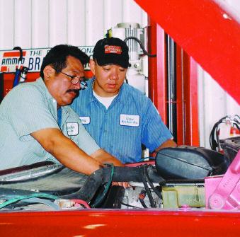 |
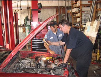
| The owner, Mikey, and ASE Certified technician discussing a fuel leak on a Volkswagon Jetta. |
Standing up and hurrying from behind the counter, Mikey smiles big and apologizes for keeping his visitor waiting a couple of minutes. He seems unusually friendly — happy even — for a repair shop owner, but it soon becomes clear why. Mikey’s is profitable and debt free, despite Mikey continuous upgrades of computer capabilities and shop equipment and an expansion in 1999 that boosted the number of bays from one to seven, which expanded the business to about 4,900 square feet. Located on Almeda Road, approximately half-way between downtown and Houston’s sprawling Medical Center complex, Midtown auto service is in a high-traffic area and doesn’t have a competitor within miles.
Mikeys customers are happy about the shop, too. On the wall opposite the counter is a framed seal of approval from AAA. Mikey’s got a 98 percent customer-satisfaction score in April. On Citysearch.com, the Web-based business-search site where customers comment on their experiences with local businesses, Mikey’s get 18 “Highly Recommended” votes out of 19 reviews.
In June, one customer wrote: “I have been to Midtown’s with both of my cars and I have been very happy with each experience. Mikey, himself, listens to your problem and explains it well, even showing you the problem directly. He always seems happy to listen, while a lot of other mechanics act irritated that you’re wasting their time. Fair, thorough and professional. That’s all I could ask of a mechanic, and Midtown’s hits a home run every time.”
The customer review, however, raises a question: If Yu, is the owner, who is Mikey? Turns out, there is no “Mikey” associated with the business. Never has been. The shop was opened in 1987, by Mikeys father Man Yu, who emigrated with his family from South Korea in 1973, when Mon was three. His father worked for several years in the Meineke Car Care Center warehouse in Pasadena, south of Houston. Man Yu didn’t even own a car in the early years, and walked to work. Sam Meineke, the Houstonian who founded the chain, admired Man Yu’s work ethic and the two men became friends, as well.
“Sam gave him a break, and asked him if he wanted to buy a store.” Mikey says. Man Yu owned a Meineke shop in southwest Houston for seven years, and in 1987 he bought the current location, which had been another Meineke shop, to open his own repair garage. “He was thinking ‘Mikey’ sounds like Meineke,” Mikey explains, “and the people in the neighborhood were used to that.” So, father and son became known as Mikey, and Mon Yu’s work shirt has a “Mikey” patch on the right front. “Everyone who walks in assumes I’m Mikey,” Mikey said. “I’ve got people coming in who were my dad’s customers and they call me junior Mikey.”
He bought the business from his father-for less than $100,000 and with monthly payments-when his father wanted to retire in 1999. He sold his cars and maxed out his credit cards for the down payment, he said. In addition to expanding the shop space, he bought new lifts, a new alignment machine and other equipment and computerized the operation. “Dad didn’t have a computer,” Mikey said. “He kept it in his head.” He says the business, which has three ASE-certified techs, has grown about 15 percent a year since 1999. Mikey’s is one of only about 200 shops in the Houston area that participate in the State of Texas emissions-control program with Advanced Engine Performance Specialist certification and the computer equipment required by the program.
Both men were self-taught mechanics, but as a young man Mon Yu saw the shop more as a way to make walking- around money than as his future source of income. “I resisted it,” he says. “I was that teenager guy who thought, I’m not taking over this dirty shop.” Still, he soon realized that doing a quick brake job was a better use of his time than doing odd jobs on an hourly basis, so he picked up additional skills. “I learned from the ground up doing everything: service adviser, ordering parts, mechanical stuff,” Mikeys says. His on-the-job training met some resistance from mechanics who were not keen on teaching the boss’s son, because it cut into their commission work. “Mechanics don’t want to teach,” he says. “They’re selfish.”
He ended the commission system and put his employees on straight salaries after taking over the shop. “The downfall is sometimes they slow down on the job; when they were on a commission, they rushed,” he said. “Sometimes I’ll get on them about that.” His employees get a week of paid vacation annually, and have the option of participating in a 401k retirement plan. Mikey said he plans to add a health-insurance plan to the benefits.
Mikey, the youngest of the three sons, has a degree in criminal justice from the University of Houston. He planned to go into law enforcement, preventing crime during his day job and moon-lighting as a security officer at night in Houston’s clubs. But like a lot of working people, having a family meant a change in plans. “I was married and my wife worried for my safety if I did take a job like that,” he said. “I was ready for the transition to this business.” When the subject turns to family, his smile returns and Mikey notes the photos on the wall of his sons’ baseball team, which Mikey’s sponsors. He happily displays family pictures on his Blackberry.
 |
| ASE Certified technician working on a motor mount for a Lexus Es300. |
Mikey likes computer technology and he prefers customers who are comfortable with it, like those who find his shop through Web search sites. “They’re sophisticated people and they’re techsavvy,” he says. “They understand there are going to be some expenses in fixing their car.” For example, these customers are likely to accept his explanation that fixing the current problem is only part of the work that should be done. If he tells them that other problems are likely down the road, based on his diagnostics, techsavvy customers are more likely to tell him to perform all the needed repairs and replacements.
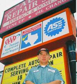 |
| The owner, Mikey, behind his shop’s sign proudly posing 18 yrs of automotive service. |
Sophisticated customers also know a fair price when they see it, and trust is an important part of Midtown’s success. As one customer wrote in May:
“I went there for an alignment because they had a better price compared to others in the downtown area. Mikey was there and took care of my car and made sure we knew what was going on, so there was no chance of surprises. Car was done exactly in the time they promised..”
Midtown Auto Service Named ‘Best Auto Shop.’![]()
Technicians’ Top 5 Favorite-Featured Article Clip-Houston,Tx

 MIKEY YU, owner ASE-certified L1 master technician
Midtown Auto Service Houston, TX
ALLDATA Information System —Shows T S B s and proper procedures of automotive repairs. Snap-on Scanner — Monitors, graphs and reads sensors; input and output. High-speed Internet — Great for finding other technicians’ opinions and to search parts options worldwide. Worldwide Emission Machine/Computer — Has dyno capabilities; reads hydrocarbon, carbon monoxide and NOx readings. Good for emissions repair. Canon Digital Camera — Enhances parts that are faulty; good for documentation of broken/faulty parts.

DEBRA FARBER, vice president
All Brand Auto Service KensingtonMD Snap-on MODIS — A powerful tool for a broad range of diagnostics and applications.Identifix — A world of information on one website. By checking www.identifix.com before starting a technical job, diagnostic time is saved because the answer is usually right there. Snap-on Smoke Machine — Many different kinds of uses, including finding intake manifold leaks. Hunter 411 4-Post Lift — Has the capacity to lift a Ford F-350 quad cab truck in the air. A heavy-duty lift that is able to accommodate those extra-large vehicles that most shops can’t service
 Mick Cipolla
Courteous Car Care Largo, FL Snap-on A/C Machine — Excellent machine, easy to operate, very accurate, great ROI. ShopKey — Fast, in depth, great flow charts, easy to navigate when downloading discs onto hard drive. Coats Tire Machine and Snap-on Wheel Balancer —We’ve been able to mount and balance tires others couldn’t.Very fast and accurate.Snap-on Vantage Scope — Easily trace out intermittents and voltage drops, and monitors wave forms. And lastly, my most important investment — the professionals I am so pleased to work with every day — Cindy Kocik, Mike Gotay and Chuck Reynolds. They set the standard by which all others will be judged. With Cindy flawlessly performing those important everyday operations that we so often take for granted, and Chuck and Mike for their commitment to their craft, to themselves and to our customers. Employing master techs has been the best investment to date — not just in income, but peace of mind — quality repairs, confidence, professionalism and a sense of family. When everyone shares the same goal, everything else falls into place.
 CHRIS “Dr. Mopar” KETTEMAN
owner Dr. Mopar’s High Performance Burlington, NC www.DRMOPARSHP1.bravehost.com The crew at Dr. Mopar’s participates in the annual AMC/Mopar “Hospice Nationals” Show, a national car show/race/swap meet to raise money for Hospice. The show is held at Roxboro Dragway in Timberlake, NC. Thanks to all those in the crew, who use these tools. Campbell-Hausfeld Air Compressor — Very reliable, never have problem with slow buildup of pressure, always quick.And last, but not least, is our 2-Ton Foldable Shop Crane. From Central Hydraulics — This has been put to good use, and doesn’t take up much space, if any, in our shop.All the above tools are just some of the many we use. We have a one-bay shop, and perform restorations, routine maintenance, high-performance motor, tranny and rear end rebuilds, all on Dodge, Chrysler, Plymouth, Jeep/AMC vehicles only.
Undercar Digest-Auto Tech Trade Magazine-Houston,Tx
![]()

![]()
Mon Yu, owner of Midtown Auto Service in Houston, never planned to follow in his father’s footsteps as a shop operator – it just turned out that way. While working on his degree in criminal justice from the University of Houston, Mon spent weekends at his father’s shop, Mikey’s Muffler & Brake. For Mon it was just a way to have some extra money for the weekends.
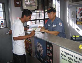 |
| The owner, Mikey, explaining to a customer a diagnostic report on a check engine light. |
To earn it, he performed the duties of porter, estimator and counterman – all at the same time. It was a start at learning the business from his father, Man Yu, who had learned shop management from a man who made a name for himself in Houston and the United States – Sam Meineke. Mon came to the United States from South Korea with his parents when he was only 3 years old. His father found employment with Sam in the heyday of muffler shops. In 1986 the franchise founder of Meineke Muffler & Brakes offered to sell the senior Yu one of his original three-bay buildings in Houston’s inner-city district. Because of his marketing sense, Man named the shop “Mikey’s” so it would sound similar to Meineke. To this day the Yu and Meineke families are friends. “I was planning on being a police officer, but my dad was at the age where he wanted to retire, so he sold the business to me,” Mon said. “Back then the American dream was to own your own business, and he said, ‘Why don’t you take over the business?” Back then this shop was only three bays.
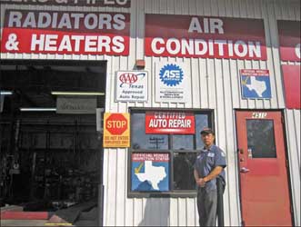 |
| Mikey, showing the front of his shop displaying his State Certification and Master ASE signs. |
In the past eight years that I’ve owned the business, I’ve increased the bays to a total of seven and I have revamped the shop. I’ve redone the floors and the outside parking lot, sixteen camera surveillance system added metal-rod fencing outside and rebuilt the entire building.” He also changed the business from a muffler and brake shop to a complete auto-repair center. Midtown’s services include engine diagnostics, alignments with the Hunter DSP600 laser aligner, electrical troubleshooting (the only one in the area), oil changes, brakes, starters and alternators, radiators and heaters, belts and hoses, air conditioning, timing belts, overheating issues, engines and head gaskets removal and replacement, muffler replacement and custom exhaust with a Huth bender.
 |
| ASE Auto Technician Vicent Poliski discussing an electrical issue with the owner about a customers car with a battery drain. |
“We are a recognized emission-repair facility, which means we have an ASE L1-certified technician, that our shop is certified and we have followed all the rules and regulations.” This allows Midtown to inspect and make emissions repairs, he said. In the case of low-income vehicle owners, the state will provide a
waiver and give the owner up to $600 to get the vehicle up to the proper emissions standards.Those repairs can be made only at a recognized facility, such as Midtown Auto Service . Mon gets quite a bit of that business, since only about 140 of the nearly 2,500 shops in the Houston metro area meet the criteria. Marcos Rodriguez is Midtown’s L1-certified technician, Mon Yoo is a Master Auto Tech and Kareem Burnley and Vincent Polisky have several ASE certifications each and are working toward their Masters. Mon supports training, paying for ASE tests that the technicians pass and any other technical classes that are being conducted in the area. Midtown also supports the community by sponsoring baseball and softball teams. Mon said Midtown’s success has a lot to do with
the shop’s location and the quality of service and repairs. In the early days under his dad’s ownership, the location was considered “the inner city” with older, lower-income housing and not much else. Today, the shop is between downtown and the Medical Center of Houston, where people from throughout the country come for cancer treatment.
 |
| ASE Auto Technician Larry Wagner installing a new Ac Delco battery. |
The area has gone through a renewal period, Mon said, with old homes and apartments being renovated. New townhouses with 1,800 square feet of living area are starting at $300,000. “It’s turned into townhouses and yuppies” moving in,” Mon said. “We’re really in a great spot on a major
intersection. Our main customers are white-collar, and we normally run about three shuttles a day to take customers downtown or to the medical complex.” Mon noted that Midtown prides itself on its customer service. “We don’t take in more work than we can handle, and we do quality work. Although in the earlier days Mikey’s repaired a lot of older Ford, GM and Chrysler products, today the shop works on a wide variety of vehicles including OBD-II domestic and most imports, as well as Lexus, Volkswagon, BMW, Audi and Jaguar models. Mon said he has no regrets about not entering the field of law enforcement. He is proud of the accomplishments he and his team have made. “One of my bragging rights is that in 2005 I was the winner on Yahoo’s search engine,” he said. “Out of 100,000 clicks, I beat out every single shop in this area. In 2006 I was winner of the Best Auto Repair Shop in houstonbest.com. In citysearch.com, in two different search engines, we were winner of best auto-repair shop.”
![]()
Midtown Auto-Voted Houston’s Auto Repair of the Year 2006/Houston,Tx
Midtown Auto Service & Repair — Voted Houston’s Auto Repair of the Year by Subscribers of The Local Newspaper.

AUTO REPAIR/CAR REPAIR/BRAKE FLUID TESTING & BRAKE FLUSHING-HOUSTON,TX
Most vehicle owners understand that dirty engine oil, transmission fluid or antifreeze can be harmful to their vehicles. What about brake fluid? Some may understand that the master cylinder reservoir should be topped off if the brake fluid level drops, but what about flushing the fluid on a regular basis? According to the Car Care Council, the brake fluid in a typical vehicle can become contaminated in two years or less. Most domestic OEMs do not have a time- or mileage-based brake fluid replacement requirement, specifying only that the fluid be inspected at regular intervals. Many import manufacturers do recommend fluid replacement at prescribed intervals.
Auto Repair/Car Repair/Car Hybrid Safety-Houston,Tx
Hybrid Safety: Important Tips That Could Save Your Life By Craig Van Batenburg, AAM
Some of you have taken my gas and electric vehicles (hybrids) class, but most haven’t. Safety is a big part of the course. The Toyota Prius and Honda Insight and Civic gas hybrids are out there. They will have accidents and you will be asked to fix them. Collision shops are usually the first to experience the difference.


I want to see you in class some day, so don’t be foolish. If you have any doubts about your ability to perform these safety steps, then leave this for someone else.
Safety in the Oven![]()